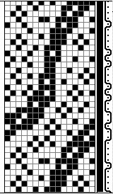
Treadling or Peg Plan Pane
The treadling pane (see illustration below) is similar to the threading pane, except that here rows represent weft threads and columns indicate treadles.
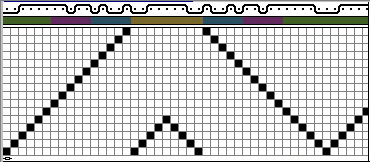
Float Diagram
The single-thread float diagram (illustration below) shows how a single thread passes through the fabric (for other ways of viewing floats, please see Warp/Weft Floats and Float Histogram). The example given here is of a diagram of a weft thread passing over and under 24 warp threads. Notice that the float is at most 3, and this thread is mostly on the front of the fabric (the front is at the top). This tells you something about the structure of the fabric at this thread. It also suggests that the color of this thread will mostly affect the front of the fabric, because this thread spends most of its time there.
(Note: the float diagrams are only displayed at magnification “8.” If you change to another display scale the float diagrams disappear. They reappear when you return to magnification 8. See “Change Scale” in the Index for information on changing scales).
You select which thread to display by moving the thread selector. There are two selectors, one for warp threads and one for weft. They are the marks shaped like (picture) and (picture) which appear along the inner edges of the threading and treadling grids (see illustration below). The thread next to the thread selector is the one which appears in the float diagram. Move the thread selectors by clicking and dragging them with the mouse.
Color Bars
The color of each thread is shown as a box within the color bar (see illustration below).